The distance between two surface data is often too far, when the surface data are reconstructed from different CT data
This page shows how to match two separate surface data.
What this page shows
Formula
3 points on the surface P \(p_1,p_2,p_3\)
3 points on the surface Q \(q_1, q_2, q_3\)
are matched by
Rotation Matrix \(M = M_q \cdot Mp ^{\mathrm{T}}\)
Translation Vector \(t = – M_q \cdot M_p ^{\mathrm{T}} \cdot p_1 + q_1\)
※ \(M_p, M_q\) are rotation matrices between the global axis and P or Q local axis.
in 4 × 4 transformation matrix,
\(
\left(
\begin{array}{ccc|c}
& & &\\
& \huge{M} & & \huge{t}\\
& & & \\
\hline
& \large{0} & & \large{1}
\end{array}
\right)
\)
Python Script
Required: python, numpy, numpy-stl
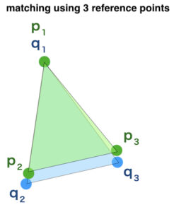
1. Surface Matching by 3 Reference Points
Picking 3 reference points on each surface can match the two surface data.
In real 3D world, position of the object can be decided by position of 3 reference points.
This page explains surface matching by 3 reference points using coordinate axes.
“Coordinate axes” may sound difficult.
Let’s think simply
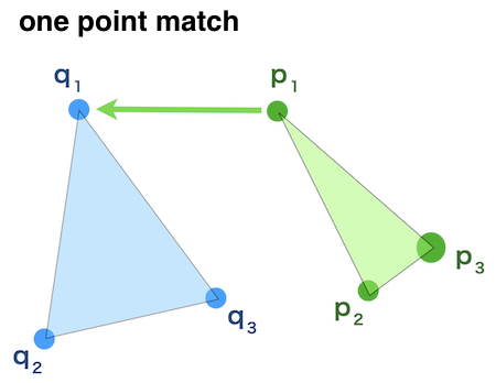
match 1 point
↓
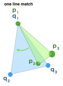
match 1 line by 2 points
↓
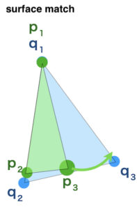
match surface by another point
Doing this process match the surfaces of two objects.
2.Axis from Vectors
Pick 3 reference points on the two surfaces individually.
3 points of the surface P (source surface) are \(p_1, p_2, p_3\).
3 points of the surface Q (target surface) are \(q_1, q_2, q_3\).
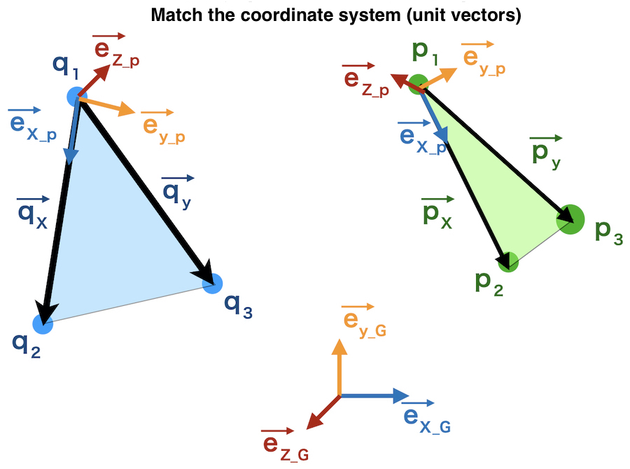
Define XYZ axis on surface P
A vector \(p_1\) ⇒ \(p_2\) is \(\overrightarrow{px} \)
A vector \(p_1\) ⇒ \(p_3\) is \(\overrightarrow{py} \)
\(p_1\) is set as the origin of P
direction of \(\overrightarrow{px} \) is x-axis
the vector vertical to \(\overrightarrow{px} \) and \(\overrightarrow{py} \) is z-axis
y-axis is vertical to z-axis and x-axis
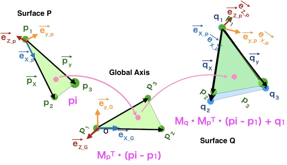
Transformation matrix between P and Q is calculated by
Matching unit vectors on surface P, Q, and Global axis.
On surface P,
unit vector of x-axis: \(\overrightarrow{ex_p} \)
\(\displaystyle \overrightarrow{ex_p} = \frac{\overrightarrow{px}}{|\overrightarrow{px} |}\)
Because a vector which is vertical to \(\overrightarrow{px}\)\(\overrightarrow{py}\) is an outer product of these two vectors,
unit vector of z-axis
\(\displaystyle \overrightarrow{ez_p} = \frac{\overrightarrow{px} \times \overrightarrow{py}}{|\overrightarrow{px} \times \overrightarrow{py}|}\)
unit vector of y-axis
\(\displaystyle \overrightarrow{ey_p} = \overrightarrow{ez_p} \times \overrightarrow{ex_p}\)
Don’t switch the components of outer product !!
\(\displaystyle \overrightarrow{ey_p} = \overrightarrow{ex_p} \times \overrightarrow{ez_p}\)
It’s not a coordinate axes.
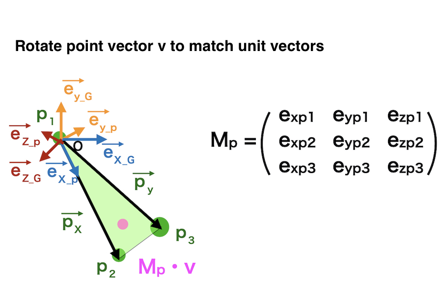
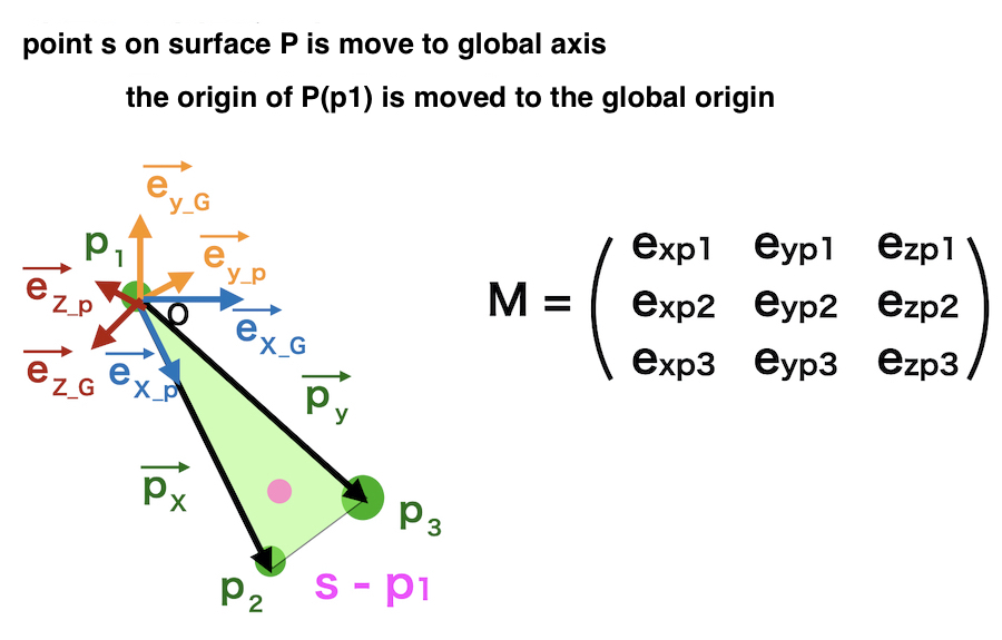
Here matrix of ex, ey, ez
\(M_p = \begin{pmatrix}
\overrightarrow{ex_p} & \overrightarrow{ey_p} & \overrightarrow{ey_p}
\end{pmatrix}\)
is a rotation matrix
In detail, each unit vector has its own xyz values like
\(\overrightarrow{ex_p} =
\left(
\begin{array}{c}
ex_{p1} \\
ex_{p2} \\
ex_{p3}
\end{array}
\right)
\) \(\overrightarrow{ey_p} =
\left(
\begin{array}{c}
ey_{p1} \\
ey_{p2} \\
ey_{p3}
\end{array}
\right)
\) \(\overrightarrow{ez_p} =
\left(
\begin{array}{c}
ez_{p1} \\
ez_{p2} \\
ez_{p3}
\end{array}
\right)
\)
\(M_p = \begin{pmatrix}
ex_{p1} & ey_{p1} & ez_{p1} \\
ex_{p2} & ey_{p2} & ez_{p2} \\
ex_{p3} & ey_{p3} & ez_{p3}
\end{pmatrix}\)
3.Transform a point on the source surface
Let’s think about the process
“Transform one point on the surface P to another surface Q”
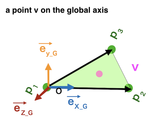
Move a point vector \(v\)
from the global axis to surface P
=> Rotate the vector \(v\)
Then move the global origin to the surface P origin \(p_1\).
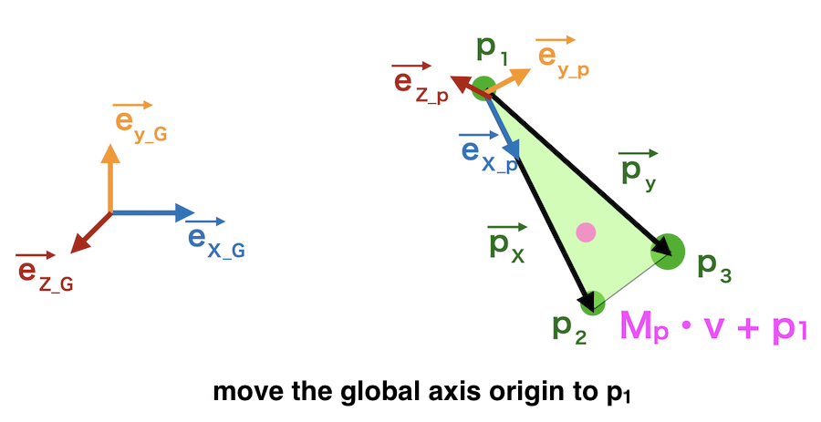
\(M_p \cdot v + p_1\)
Conversely,
Move a point “s” on surface P to the global axis.
At first,
the origin of surface P is moved to the global origin.
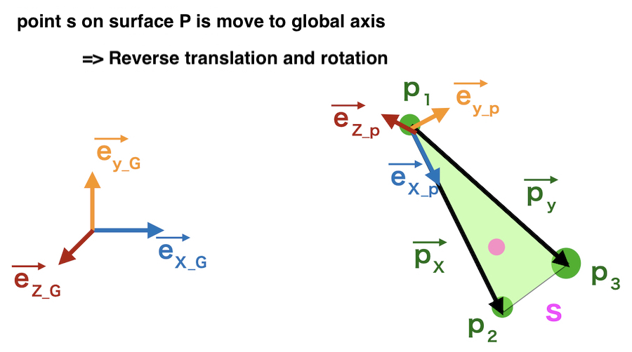
Then rotate the point backward.
Inverse matrix of the previous rotation matrix is used.
for rotation matrix (M),
\(M^{-1} = M^{\mathrm{T}}\)
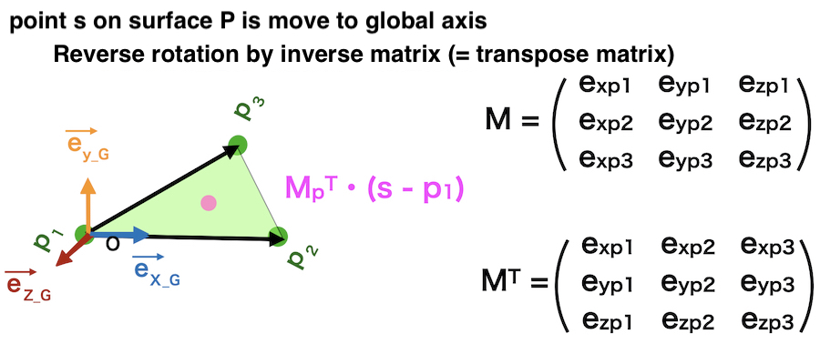
\(M_p ^{\mathrm{T}} \cdot (s – p_1)\)
In the same way,
Move a point “u” in the global axis
to a point on the surface Q.
\(M_q \cdot u + q_1\)
These processes are integrated.
Move a point pi on surface P
is moved onto surface Q by
\(M_q \cdot (M_p ^{\mathrm{T}} \cdot (pi – p_1)) + q_1\)
\(M_q \cdot Mp ^{\mathrm{T}} \cdot pi – M_q \cdot M_p ^{\mathrm{T}} \cdot p_1 + q_1\)

In the formula can be described by using
Rotation matrix \(M\)
\(M = M_q \cdot Mp ^{\mathrm{T}}\)
and translation vector \(t\)
\(t = – M_q \cdot M_p ^{\mathrm{T}} \cdot p_1 + q_1\)
as
\(M \cdot p_i + t\)


4.Write Code with Python
These processes can be written in a script with python.
import numpy as np

def transform_matrix(p1, p2, p3, q1, q2, q3):
    """
    Input: 3 reference points on the surface P (p1, p2, p3) and Q(q1, q2, q3)
           all points data are numpy.array
    Output: rotation matrix M(3x3), translation vector t
    """

    #calculate parameters for surface P
    #vectors px, py
    px = p2 - p1
    py = p3 - p1
    #unit vectors (ex, ey, ez)
    ex_p = px / np.linalg.norm(px)
    ez_p = np.cross(px, py) / np.linalg.norm(np.cross(px, py))
    ey_p = np.cross(ez_p, ex_p)
    # align the unit vectors in longitudinal axis
    Mp = np.array([ex_p, ey_p, ez_p]).T

    #same process in surface Q
    qx = q2 - q1
    qy = q3 - q1
    ex_q = qx / np.linalg.norm(qx)
    ez_q = np.cross(qx, qy) / np.linalg.norm(np.cross(qx, qy))
    ey_q = np.cross(ez_q, ex_q)
    Mq = np.array([ex_q, ey_q, ez_q]).T

    #calculate rotation matrix M and translation vector t

    M = np.dot(Mq, Mp.T)
    t = - np.dot(np.dot(Mq, Mp.T), p1) + q1
    return M, t
5.Example of the CT data analysis
As an example, the surface data of scapula bones are used.
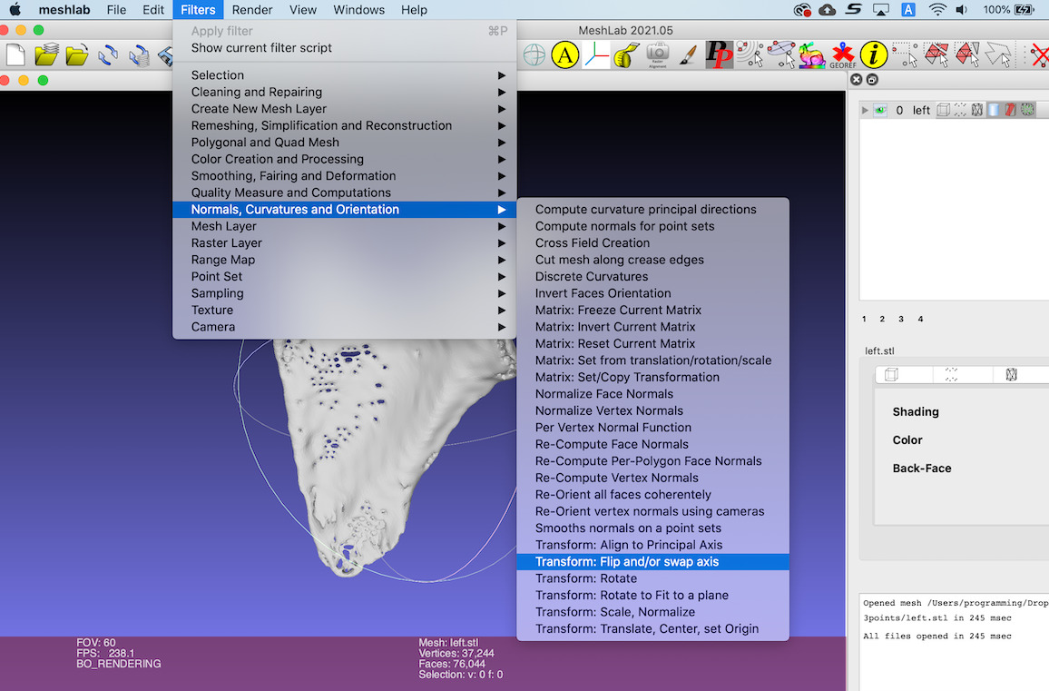
Flip the surface data of the left scapula.
this process can be done by Meshlab
MeshLab 「Filters」→ 「Normals, Curvatures and Orientation」→「Flip and/or swap axis」
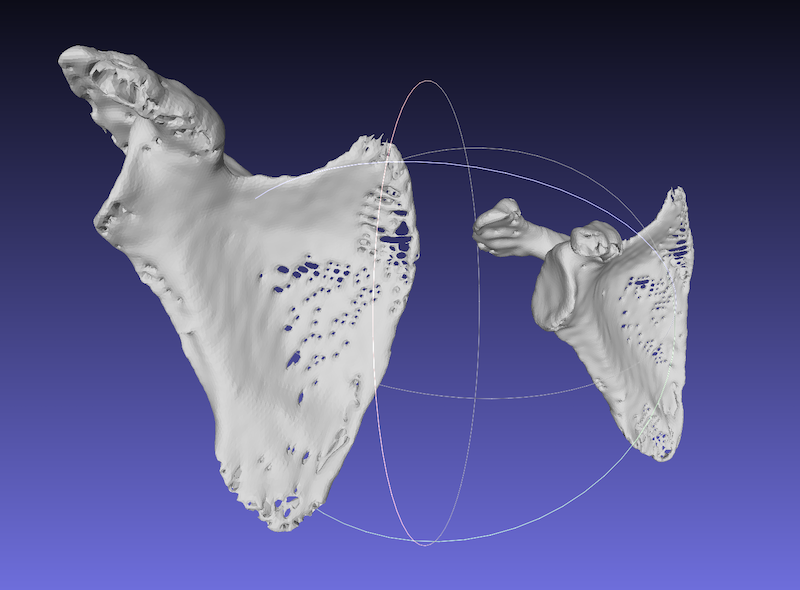
Right and Left scapula bones.
Two surfaces are reconstructed apart.
3 references point on surface P are picked and saved in ‘.pp’ file.
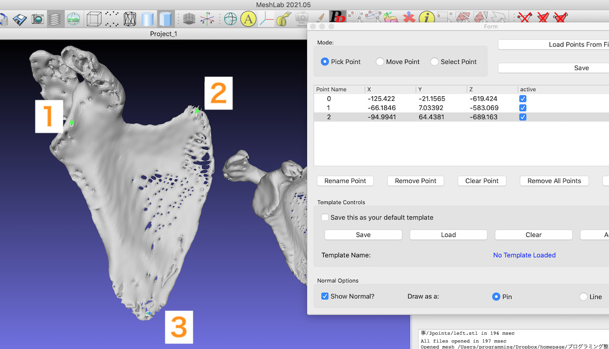
3 references point on surface Q are also picked and saved.
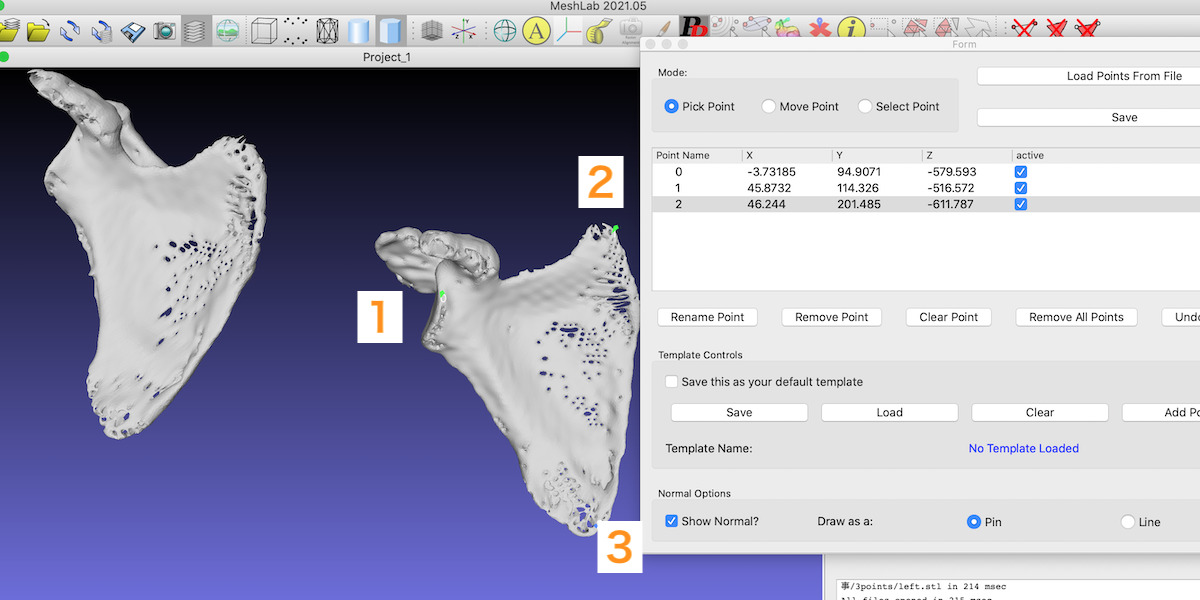
It’s important to pick 3 points in the similar order (e.g. clockwise).
Run the next script in the folder which contains the surface data and ‘.pp’ file.
import point_class
import rough_match
"""read 3 reference points from .pp file"""
right_points = point_class.MeshlabPp('right.pp')
# 3 reference point on the right scapula
left_points = point_class.MeshlabPp('left.pp')
# 3 reference point on the left scapula
p1, p2, p3 = right_points.point_list
q1, q2, q3 = left_points.point_list
M, t = rough_match.transform_matrix(p1, p2, p3, q1, q2, q3)

#calculate rotation matrix and translation vector
print(M)
# rotation matrix
# [[ 0.9590293  -0.05833918 -0.27723519]
#  [-0.01219987  0.96915644 -0.24614419]
#  [ 0.28304412  0.23944172  0.92873769]]


print(t)
# translation vector
# [-56.40921238 -38.58660633  36.25468863]
The result is shown by numpy-stl.
numpy-stl can be installed by
pip install numpy-stl
Transform right.stl by rotation matrix\(M\), translation vector\(t\)
import numpy as np
from stl import mesh

right_stl = mesh.Mesh.from_file('right.stl')
transform_matrix = np.identity(4)
transform_matrix[:3, :3] = M
transform_matrix[:3, 3] = t
print(transform_matrix)
# [[ 9.59029296e-01 -5.83391829e-02 -2.77235188e-01 -5.64092124e+01]
#  [-1.21998734e-02  9.69156438e-01 -2.46144190e-01 -3.85866063e+01]
#  [ 2.83044118e-01  2.39441723e-01  9.28737685e-01  3.62546886e+01]
#  [ 0.00000000e+00  0.00000000e+00  0.00000000e+00  1.00000000e+00]]
right_stl.transform(transform_matrix)
right_stl.save('right_trans.stl')
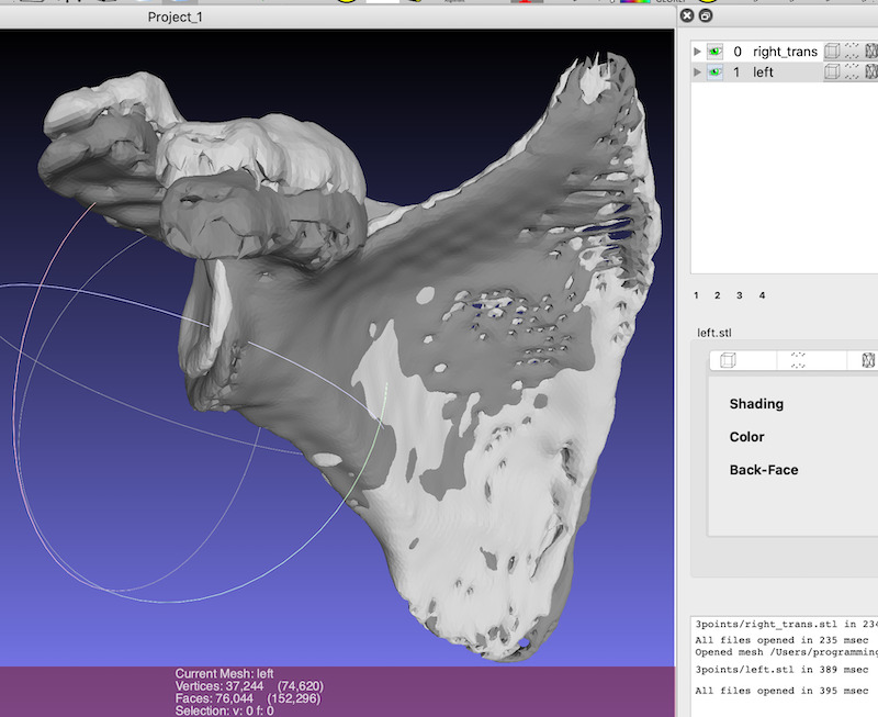
The source surface can be translated close to the target surface.


ICP algorithm for surface matching using python, vtk
Supplement : Read .pp file from Meshlab by Python Script
Point data in “.pp” files can be read using python script.
This is a example
“point_class.py”
<!DOCTYPE PickedPoints>
<PickedPoints>
<DocumentData>
<DateTime date=”2021-09-20″ time=”06:50:29″/>
<User name=”programming”/>
<DataFileName name=”right.stl”/>
<templateName name=””/>
</DocumentData>
<point x=”-125.42151″ active=”1″ name=”0″ y=”-21.156488″ z=”-619.42358″/>
<point x=”-66.18457″ active=”1″ name=”1″ y=”7.0339193″ z=”-583.06927″/>
<point x=”-94.994087″ active=”1″ name=”2″ y=”64.438072″ z=”-689.16339″/>
</PickedPoints>
<!DOCTYPE PickedPoints>
<PickedPoints>
<DocumentData>
<DateTime date=”2021-09-20″ time=”06:52:11″/>
<User name=”programming”/>
<DataFileName name=”left.stl”/>
<templateName name=””/>
</DocumentData>
<point y=”94.907089″ x=”-3.7318501″ active=”1″ z=”-579.5929″ name=”0″/>
<point y=”114.32571″ x=”45.873207″ active=”1″ z=”-516.57227″ name=”1″/>
<point y=”201.48509″ x=”46.244011″ active=”1″ z=”-611.78662″ name=”2″/>
</PickedPoints>
import numpy as np

class MeshlabPp(object):
    """
    object : .pp file
    method ".point_list" return the point list
    """
    def __init__(self, file_name):
        self.point_list = read_pp(file_name)

def read_pp(file_name):
    point_list = []
    with open(file_name) as f:
        line = f.readline()
        while line:
            inside_line = line[line.find('<') + 1: line.find('/>')]
            words = inside_line.split(' ')
            if words[0] == 'point':
                for word in words:
                    if 'x=' in word:
                        x = float(word.split('"')[1])
                    elif 'y=' in word:
                        y = float(word.split('"')[1])
                    elif 'z=' in word:
                        z = float(word.split('"')[1])
                point_list.append(np.array([x, y, z]))
            line = f.readline()
    return point_list